You are using an out of date browser. It may not display this or other websites correctly.
You should upgrade or use an alternative browser.
You should upgrade or use an alternative browser.
Signet-ficant Other
- Thread starter Dr.Jass
- Start date
Dr.Jass
Pastor of Muppets
When last we left our valiant little, er, Valiant she had a new front frame rail, subframe connectors, and shiny new floors. The chassis end of the 4-speed conversion was done, including the steering column. Things were looking good, so of course the car then sat virtually untouched for well over a year. She was snowbound for the winter of '18-'19, and Stretchy-Poo was busy with something--I can't remember if it was a Chris Craft or Pinewood Derby car, but I know it was wood--so poor Agnes was back-burner stuff for the time being.
Perhaps it was because we knew what lay ahead: Squares, levels, chalk-lines, angle finders... even an honest-to-God protractor at one point. This was where we would one-up the drunken Poletown boys in attention to detail, once we shored up what turned out to be a little worse than we thought. That scary picture above is Our Man Elastic looking through the driver's-side wheelhouse. Rather, where it once was.
If this process seems lengthy, rest assured I am really skimming through it. The car went into Stretch's garage in April of '19 and did not emerge until October. Five months. We weren't after it every weekend, but we were in there a lot... most importantly, damn it, she was in there again.
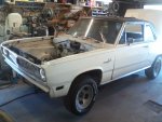
We started by taking stock of exactly what it was with which we were working... not much, as it happened.
The driver's side rail was, in biblical terms, smote at least a foot forward of the just-as-bad former shackle mount. To quote the fine folks of the planet Krikkit upon their discovery of the beauty and awe of the Universe around them, "It'll just have to go."
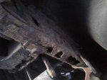

As so often is the case with these cars, there wasn't exactly much to which we could weld any replacement bits, either... luckily, the really-bad part in this picture is not where the framerail goes:
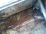
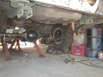
That would have to go as well... and go, it did. It all did, starting with the rear suspension and fuel tank:
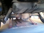
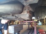
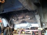
Other than the gas tank, everything went into the scrap pile... nothing's going back, particularly those insipid air shocks. The 7¼" axle is worthless for even a trailer, its shock plates won't work on any other axle, and the springs were obviously being shored up by the moronic shock absorbers.
We quickly broke out the cutoff-wheel-equipped angle grinder, and hacked away with wild abandon until we found solid metal with which to work.
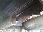
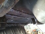
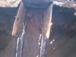
At that point, the enormity of the trunk rot became evident, so we amputated a pretty good chunk of trunk floor as well, again cutting until we found something solid:
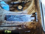
And then we promptly made what would be the easiest patch on the back half of the car (bottom of photo, beneath the gaping maw):

Really, that was quite a bit of progress for the first day back at 'er after nearly a year and a half pause. We were satisfied with what we'd achieved and started to strategize the unfuckery before calling it quits for the day.
Perhaps it was because we knew what lay ahead: Squares, levels, chalk-lines, angle finders... even an honest-to-God protractor at one point. This was where we would one-up the drunken Poletown boys in attention to detail, once we shored up what turned out to be a little worse than we thought. That scary picture above is Our Man Elastic looking through the driver's-side wheelhouse. Rather, where it once was.
If this process seems lengthy, rest assured I am really skimming through it. The car went into Stretch's garage in April of '19 and did not emerge until October. Five months. We weren't after it every weekend, but we were in there a lot... most importantly, damn it, she was in there again.

We started by taking stock of exactly what it was with which we were working... not much, as it happened.
The driver's side rail was, in biblical terms, smote at least a foot forward of the just-as-bad former shackle mount. To quote the fine folks of the planet Krikkit upon their discovery of the beauty and awe of the Universe around them, "It'll just have to go."


As so often is the case with these cars, there wasn't exactly much to which we could weld any replacement bits, either... luckily, the really-bad part in this picture is not where the framerail goes:

That would have to go as well... and go, it did. It all did, starting with the rear suspension and fuel tank:


Other than the gas tank, everything went into the scrap pile... nothing's going back, particularly those insipid air shocks. The 7¼" axle is worthless for even a trailer, its shock plates won't work on any other axle, and the springs were obviously being shored up by the moronic shock absorbers.
We quickly broke out the cutoff-wheel-equipped angle grinder, and hacked away with wild abandon until we found solid metal with which to work.


At that point, the enormity of the trunk rot became evident, so we amputated a pretty good chunk of trunk floor as well, again cutting until we found something solid:

And then we promptly made what would be the easiest patch on the back half of the car (bottom of photo, beneath the gaping maw):

Really, that was quite a bit of progress for the first day back at 'er after nearly a year and a half pause. We were satisfied with what we'd achieved and started to strategize the unfuckery before calling it quits for the day.
Dr.Jass
Pastor of Muppets
The next time we got to it, we wanted to do some fun stuff too... hot-roddy stuff. So, we started with the really-fun bit: cutting. There was some sound logic behind this, though; with the missing trunk and rail, there was less weight back there to potentially distort the axle kickup during its surgery. *ahem*bullshit
We laid out our cut lines, and the surgery began:


In this shot, Stretch-a-Sketch has installed a feather in a die grinder to find out if she's ticklish near her bum. Wouldn't want an involuntary twitch during the incision.
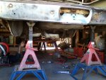
One almost feels bad about cutting away perfectly-good metal. Then one remembers that the car is worthless '69 Valiant, which is/was a also a raging pile of crap, and one dismisses any potential guilt out-of-hand.
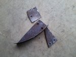
Fitting up the LH inboard spring pocket, which conveniently bolts into the holes where the leaf spring hanger was formerly installed. The beef of the US Car Tool parts is considerably greater than that of the old MP spring-relocation kit. See that angle finder? Pure class, I tell ya... we really left no stone unturned during this.
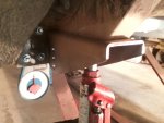
"Can we weld now?! Huh?! Canwecanwecanwe?!?"
"Yes, my flexible little friend, go ahead and weld it in."
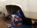
Stretch did the LH side, after which I burned in the RH. Yes, I added stiffener plates with plug welds atop the already-stout parts, more to shore up the otherwise-butt-weld-only joint to the original frame. Call me paranoid, but a leaf spring popping free during a 100+MPH quarter-mile pass doesn't appeal to me.
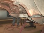
"But Jassinine," you ax, "What of the decimated frame rail?"
Worry not, camper. That was addressed as well. Unfortunately, most of the fabrication and process photos are currently stuck on a PC that won't boot, so we go directly from 'carved out' to 'completely repaired with attendant overkill', sadly skipping over Stretchpants' scratch fabrication of a new, stronger than original (if virtually useless), shackle mount. Suffice to say, there are plug-welded fish plates inside the original rail mated to the new section of box-section .080"-wall 2x3 tubing, which is both plug- and lap-welded to the (patched) trunk floor. You'll also notice we added a wraparound gusset around the shackle tube, which turned out to be 100% superfluous as well (we'll get to that).


The passenger's side, which was curiously strong in comparison to the driver's, required just a little work, largely so we'd be working with the same dimensions on both sides of the car rather than having to make adjustments side-to-side. That's how error gets introduced, and error is why cars don't go straight. I like straight.
We laid out our cut lines, and the surgery began:


In this shot, Stretch-a-Sketch has installed a feather in a die grinder to find out if she's ticklish near her bum. Wouldn't want an involuntary twitch during the incision.

One almost feels bad about cutting away perfectly-good metal. Then one remembers that the car is worthless '69 Valiant, which is/was a also a raging pile of crap, and one dismisses any potential guilt out-of-hand.

Fitting up the LH inboard spring pocket, which conveniently bolts into the holes where the leaf spring hanger was formerly installed. The beef of the US Car Tool parts is considerably greater than that of the old MP spring-relocation kit. See that angle finder? Pure class, I tell ya... we really left no stone unturned during this.

"Can we weld now?! Huh?! Canwecanwecanwe?!?"
"Yes, my flexible little friend, go ahead and weld it in."

Stretch did the LH side, after which I burned in the RH. Yes, I added stiffener plates with plug welds atop the already-stout parts, more to shore up the otherwise-butt-weld-only joint to the original frame. Call me paranoid, but a leaf spring popping free during a 100+MPH quarter-mile pass doesn't appeal to me.

"But Jassinine," you ax, "What of the decimated frame rail?"
Worry not, camper. That was addressed as well. Unfortunately, most of the fabrication and process photos are currently stuck on a PC that won't boot, so we go directly from 'carved out' to 'completely repaired with attendant overkill', sadly skipping over Stretchpants' scratch fabrication of a new, stronger than original (if virtually useless), shackle mount. Suffice to say, there are plug-welded fish plates inside the original rail mated to the new section of box-section .080"-wall 2x3 tubing, which is both plug- and lap-welded to the (patched) trunk floor. You'll also notice we added a wraparound gusset around the shackle tube, which turned out to be 100% superfluous as well (we'll get to that).


The passenger's side, which was curiously strong in comparison to the driver's, required just a little work, largely so we'd be working with the same dimensions on both sides of the car rather than having to make adjustments side-to-side. That's how error gets introduced, and error is why cars don't go straight. I like straight.

Dr.Jass
Pastor of Muppets
The Science Project.
OK, it's really more the maths but who ever heard of a math project?
Look closely, and you'll see why the gussets around the rear shackle tubes were wholly unnecessary. Those ain't shackles bolted to the hind ends of the springs, my chums. Those, my friends, are spring sliders. I bought 'em for the Imperial, but decided to learn the ins and outs, the whys and wherefores of them on a car where a little bit of rickety clatter won't bother me as much.
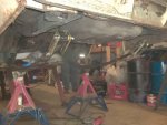
We started the initial layout of their installation with them flat against the frame rails, which really would probably have been fine for this application, and most others for that matter:

We then commenced to making sure the springs were straight and parallel by using strings as guides to which they could be aligned:
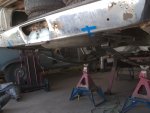
Now we get to the maths bit... remember all those times in school when you complained that you'd never use this crap in real life? I did, and I was glad I remembered sine, cosine and tangent when we decided to go full-bore on the sliders.
For sliders to work optimally, the rear eye bolt needs to travel along the line formed by itself and the front eyebolt. We mocked it up with the car sitting on its own weight, and determined that line to be at a 5½° angle to the rear frame rail. How does one come up with that? Well, since box-section tubing doesn't have square corners, measuring from the edge doesn't work well. I laid it on the bench, measured a distance from the bench to the metal in two places, scribed a line, then repeated it on the other side.
Knowing the length of the mount, and that I needed a 5½° angle to it, I simply multiplied the length of the part by the cosine of 5½°, and I had the height I needed for the tall side of the angle mount. I marked that distance for both sides of both mounts, and scribed my lines:

After careful cutting, I checked my work. Go ahead, blow it up and check it yourself. This is what they refer to in trigonometry as "fucking nailing it":
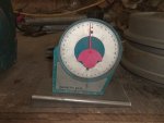
After a little prep work, welding, and some self-etching primer we checked the angle of the slot in the sliders, and damned if didn't have us a perfectly scienced leaf-spring slider arrangement:
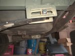
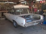
We set the old girl down, and checked out how it sat. I also wanted to get a "feel" for the sliders; a first impression if there was a noticeable difference. This is the first photo taken of Agnes sitting on her final suspension, both front and rear:
And what, you may ask, of that hot, steamy slider action? First impression was "un-fucking-believable!" It's quite different from pushing down on the rear of a car with shackles. There is literally no resistance--it just glides through its travel, thanks to the roller bearings on which the sliders travel. When one considers that these Super Stock springs could almost pass for ¾-ton truck springs, it's amazingly compliant due to total lack of bushing squish, bind, or stiction. The bushings that come with the sliders are solid bronze to keep the pin perfectly centered in the spring.
The only drawback I expect is some rattle, as there's needed clearance between the bearing and whichever ramp it isn't currently using, so on compression/rebound there will be a clunk. Also, the spring is not perfectly tight inside the slider either: there's side clearance that could cause rattles when the springs move laterally in that space. There's not much I can do about the former, but my solution for the latter was to order some heavy-duty Teflon washers that don't quite take up all the clearance, but should remove enough of it to both allow total freedom of movement and provide some cushion during side-loading. No stones unturned.
I should probably mention: It's not that I care too much about Agnes clunking and rattling her way down the quarter. It's entirely whether sliders will be feasible on the Imperial. I fully intend to keep every luxury that car provided originally, add a few, and still have that Imperial ride quality--and sound.
Next go-round, we'll talk about improvements to the front end in terms of structure and stiffness. If you've not yet noticed, those inner fenders are a tad sketchy due to our old friend rust.
OK, it's really more the maths but who ever heard of a math project?
Look closely, and you'll see why the gussets around the rear shackle tubes were wholly unnecessary. Those ain't shackles bolted to the hind ends of the springs, my chums. Those, my friends, are spring sliders. I bought 'em for the Imperial, but decided to learn the ins and outs, the whys and wherefores of them on a car where a little bit of rickety clatter won't bother me as much.

We started the initial layout of their installation with them flat against the frame rails, which really would probably have been fine for this application, and most others for that matter:

We then commenced to making sure the springs were straight and parallel by using strings as guides to which they could be aligned:

Now we get to the maths bit... remember all those times in school when you complained that you'd never use this crap in real life? I did, and I was glad I remembered sine, cosine and tangent when we decided to go full-bore on the sliders.
For sliders to work optimally, the rear eye bolt needs to travel along the line formed by itself and the front eyebolt. We mocked it up with the car sitting on its own weight, and determined that line to be at a 5½° angle to the rear frame rail. How does one come up with that? Well, since box-section tubing doesn't have square corners, measuring from the edge doesn't work well. I laid it on the bench, measured a distance from the bench to the metal in two places, scribed a line, then repeated it on the other side.
Knowing the length of the mount, and that I needed a 5½° angle to it, I simply multiplied the length of the part by the cosine of 5½°, and I had the height I needed for the tall side of the angle mount. I marked that distance for both sides of both mounts, and scribed my lines:

After careful cutting, I checked my work. Go ahead, blow it up and check it yourself. This is what they refer to in trigonometry as "fucking nailing it":

After a little prep work, welding, and some self-etching primer we checked the angle of the slot in the sliders, and damned if didn't have us a perfectly scienced leaf-spring slider arrangement:


We set the old girl down, and checked out how it sat. I also wanted to get a "feel" for the sliders; a first impression if there was a noticeable difference. This is the first photo taken of Agnes sitting on her final suspension, both front and rear:

And what, you may ask, of that hot, steamy slider action? First impression was "un-fucking-believable!" It's quite different from pushing down on the rear of a car with shackles. There is literally no resistance--it just glides through its travel, thanks to the roller bearings on which the sliders travel. When one considers that these Super Stock springs could almost pass for ¾-ton truck springs, it's amazingly compliant due to total lack of bushing squish, bind, or stiction. The bushings that come with the sliders are solid bronze to keep the pin perfectly centered in the spring.
The only drawback I expect is some rattle, as there's needed clearance between the bearing and whichever ramp it isn't currently using, so on compression/rebound there will be a clunk. Also, the spring is not perfectly tight inside the slider either: there's side clearance that could cause rattles when the springs move laterally in that space. There's not much I can do about the former, but my solution for the latter was to order some heavy-duty Teflon washers that don't quite take up all the clearance, but should remove enough of it to both allow total freedom of movement and provide some cushion during side-loading. No stones unturned.
I should probably mention: It's not that I care too much about Agnes clunking and rattling her way down the quarter. It's entirely whether sliders will be feasible on the Imperial. I fully intend to keep every luxury that car provided originally, add a few, and still have that Imperial ride quality--and sound.
Next go-round, we'll talk about improvements to the front end in terms of structure and stiffness. If you've not yet noticed, those inner fenders are a tad sketchy due to our old friend rust.
Dr.Jass
Pastor of Muppets
Front of the class, this guy... regular apple-polisher.SOHCAHTOA!
thrashingcows
Drowning deep in my sea of loathing...so I'm
over the years, I've actualy found LESS crap in my eyes wearing nothing, and the only thing i can figure is that you squint and are twice as carefull, where with full protection your wide eyed n fearless, be thankfull you werent at the DR getting them to dremel your eyeball...it SUCKS
How's the eyeball feeling these days?
The eyeball's great. It healed pretty quickly with no lingering effects.
I had the same thing happen years ago, was wearing safety goggles too and the sucker ricocheted through the vent and into my eye. I had to have the dremel treatment as well and recently had to get a CAT scan and because of this injury I had to get an X-ray of my head to confirm that there was no metal in my eyes before they would do the scan.
Guess it's bad to have the big magnet pulling little pieces of metal out of your eye...
Dr.Jass
Pastor of Muppets
Well you do now, and there'll be a full review of the suspension once she's finally self-motivated... that will include a Hellwig front swaybar and KYB Gas-A-Just shocks at all four corners, though experience tells me there won't be any surprises on those two items.Those sliders are pretty trick! I've never actually known anyone to use them.
I'm really interested to see how the car reacts at the track with the sliders and a pinion snubber working with the Super Stocks, which are technically too heavy for the car but are also what I had lying around (like most of this entire build).
Dr.Jass
Pastor of Muppets
I don't expect the thing to ride like the Imperial, but like I said I was very surprised by the suspension compliance just pushing it down by hand. I think the roller bearings will help over minor road irregularities, allowing the springs to work more easily. It'll still hammer like a buckboard over potholes and bad railroad tracks, I've little doubt.
Dr.Jass
Pastor of Muppets
With the rear suspension fairly well sorted, it was time to revisit the front. The inner fenders were a bit dicey from rust, and I had no intention of spending loot on good ones or making ugly patches to what was there... so, I ignored that entirely.
We started by doing something we dreaded: removing the fenders. Way back at the start, we'd begun to remove the LH fender. The crunching noises (and no real need to remove it) stopped us. We installed the frame rail with the fender in place, no problem. This time, we really had little choice. Most of the bolt holes simply ripped away, leaving us with bolts still in the fenders, threaded into speed nuts still grasping chunks of inner fender. It was not pretty. We simply cut out those sections entirely, back to where we found useful metal.
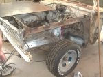
New sections were made by Stretch on his homegrown brake, giving us both butt welds to the original fender flange sections and plug welds on the vertical. This ain't rocket surgery--once the fender's on it'll never be seen, and it doesn't even affect panel alignment. Simple, effective, and cheap.
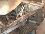
Holes were drilled & ovalled after laying them out, and the whole shebang was etch primed from a rattle can. We later rattle-canned them white. We were hooked at reinstallation time... but there was much more to do before then.

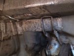
While Stretch was working on that, I'd been cleaning up the areas critical to the next project. This is the passenger's-side front shock tower:
And this is the passenger's-side front shock tower on steroids, er, US Car Tools' excellent shock tower braces:

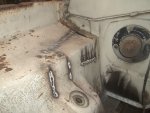
Unlike most of their stuff, this part didn't fit particularly well. It's no fault of theirs; this car was crashed on this side at one point and some of the repair work done with a ball-peen hammer. The car did drive well, though, so I just strengthened it as-was. Note the daylight showing through the inner fender to the upper left of the brace--that was what I was actually fixing here, in my own furtive way. The welds may not look spectacular, but they certainly penetrated. You can see the extent of the topside damage better here, since the brace isn't in the way.
All buttoned up and ready for paint and undercoating.

We switched sides, with Stretch adding fender-mount tabs here while I repeated the brace installation on the other side. No need to bore you with mirror-image progress, but the other side went together much more easily. Thanks to Big McLargehuge, we had a nice place to hang a fender when the time came.
That would be the extent of the chassis mods themselves, so we put the fenders back on and pushed her outside until the next round could happen. This rotten little A-body is really starting to grow on me.

We started by doing something we dreaded: removing the fenders. Way back at the start, we'd begun to remove the LH fender. The crunching noises (and no real need to remove it) stopped us. We installed the frame rail with the fender in place, no problem. This time, we really had little choice. Most of the bolt holes simply ripped away, leaving us with bolts still in the fenders, threaded into speed nuts still grasping chunks of inner fender. It was not pretty. We simply cut out those sections entirely, back to where we found useful metal.

New sections were made by Stretch on his homegrown brake, giving us both butt welds to the original fender flange sections and plug welds on the vertical. This ain't rocket surgery--once the fender's on it'll never be seen, and it doesn't even affect panel alignment. Simple, effective, and cheap.

Holes were drilled & ovalled after laying them out, and the whole shebang was etch primed from a rattle can. We later rattle-canned them white. We were hooked at reinstallation time... but there was much more to do before then.

While Stretch was working on that, I'd been cleaning up the areas critical to the next project. This is the passenger's-side front shock tower:

And this is the passenger's-side front shock tower on steroids, er, US Car Tools' excellent shock tower braces:

Unlike most of their stuff, this part didn't fit particularly well. It's no fault of theirs; this car was crashed on this side at one point and some of the repair work done with a ball-peen hammer. The car did drive well, though, so I just strengthened it as-was. Note the daylight showing through the inner fender to the upper left of the brace--that was what I was actually fixing here, in my own furtive way. The welds may not look spectacular, but they certainly penetrated. You can see the extent of the topside damage better here, since the brace isn't in the way.

All buttoned up and ready for paint and undercoating.

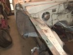
We switched sides, with Stretch adding fender-mount tabs here while I repeated the brace installation on the other side. No need to bore you with mirror-image progress, but the other side went together much more easily. Thanks to Big McLargehuge, we had a nice place to hang a fender when the time came.

That would be the extent of the chassis mods themselves, so we put the fenders back on and pushed her outside until the next round could happen. This rotten little A-body is really starting to grow on me.

Dr.Jass
Pastor of Muppets
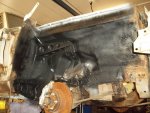
The next time Agnes got some attention, I was flying solo and we'd brought the car to work so I could use the hoist. Nothing too exciting here, just me with rattle cans of paint, truck-bed liner, and undercoating. Yes, the bedliner and undercoating add weight, but if you've ever had a rock hit the inner fender of a car completely devoid of it, you know how loud it is. I don't like loud unless it's header bellow.


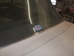
Once again, after the boredom of shooting chemicals, I wanted to do some fun stuff I'd had in mind for awhile. Seeming appropriate since I was born in '70 and the car's a '69 (and falling directly into the "make 'em wonder" category) this little gem landed in the center of the back window:

On the other hand, falling into the "no shit, Sherlock" were these peachy little emblems I just had to have, which announced the two-barrel 273 or 318 to the world originally:
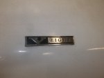
Yes, that's cracked plastic filler, which was so thick in this area that I actually had to figure out an alternate means of installing this one. Sadly, I find qualities like this endearing in this forsaken little crapbasket.
After once again installing the fenders--I had to take them off to install the emblems--I once again relegated Ms. Agnes to the outside world. She looks better every time I do, though.
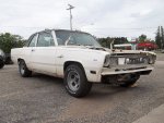

Oh, if any of you are wondering why the car sits so low with 3,400lb. B/E-body Super Stock springs under it, I had the local spring shop de-arch them a whopping six inches way back when I still had my LeBaron. It might ride like a truck, but I wasn't interested in it looking like one!


Once again, after the boredom of shooting chemicals, I wanted to do some fun stuff I'd had in mind for awhile. Seeming appropriate since I was born in '70 and the car's a '69 (and falling directly into the "make 'em wonder" category) this little gem landed in the center of the back window:


On the other hand, falling into the "no shit, Sherlock" were these peachy little emblems I just had to have, which announced the two-barrel 273 or 318 to the world originally:

Yes, that's cracked plastic filler, which was so thick in this area that I actually had to figure out an alternate means of installing this one.
After once again installing the fenders--I had to take them off to install the emblems--I once again relegated Ms. Agnes to the outside world. She looks better every time I do, though.


Oh, if any of you are wondering why the car sits so low with 3,400lb. B/E-body Super Stock springs under it, I had the local spring shop de-arch them a whopping six inches way back when I still had my LeBaron. It might ride like a truck, but I wasn't interested in it looking like one!
Dr.Jass
Pastor of Muppets
Braking Up is Hard to Do...
So I left the bending to Jaynormous. His years of experience in undercar work paid dividends here, and I was in no position to challenge his bending skills. The work speaks for itself. The only preformed lines on the car are on the rear axle itself; Stretch bent the rest freehand. The lines are all in NHRA-approved locations; we don't want Mr. Tech to not allow us on the track because a driveshaft or clutch could come apart and hamper our ability to stop the car. Nobody makes those kind of lines, kids.
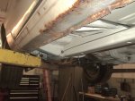
Starting at the rear-axle hose fitting, he went up to the floor then looped around the frame:
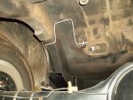
He then went down to the leaf-spring outrigger, where I installed a grommet and slipped a slitted section of rubber hose over the line to protect it from the metal's edge:
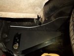
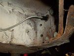
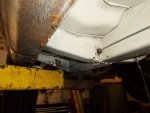
He then went forward to the front rocker outrigger, which we'd decided was the best place for the adjustable proportioning valve. It's safe from road debris and prying eyes here, yet easily accessed during the adjustment procedure:
Next, we needed to get out of the master cylinder and down to both the prop valve and line lock... that meant curly-Q lines coming out of the master. The line furthest from the firewall is the rear line, which takes the path the parking-brake cable used to use through the inner fender and makes its way to the prop valve. It was an impressive single-piece accomplishment.
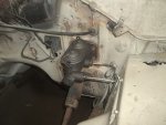
It's sorta hard to see in this picture, but we're fully plumbed at the prop valve.
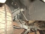
Next, the line lock was mounted under the battery tray and the rearmost line from the master cylinder was routed directly into the back of it. Another gorgeous single-piece bend linked the side outlet of the tee on the output to the stainless left-side brake hose:

It was at this point that we realized we were out of brake line, so finishing the other side would have to wait until more arrived. That happened a week later, along with some other stuff, but we'll tidy up this segment now.
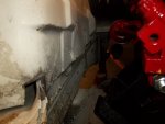
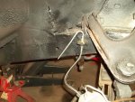
This was how the right-hand line was routed. The NHRA (and hence, the nearest track) are not fans of lines on the firewall over the clutch housing, so we went forward. It sits under the radiator, passes along the RH rail, then loops under it to connect to the RH caliper's hose. Yet another example of Stretch's single-line bending mastery... it's a huge run.


Other than a battle to sort out the rear brake hose and its adapter fitting, that pretty much does it for the brakes. You no doubt noticed that the engine found its way in there the same day. That bit, and all the struggles it represented, are coming soon. But, as a final sayonara to the braking system, here's a shot with the battery tray back in place...
"Line lock? I don' know nuffin' 'bout no line lock."

So I left the bending to Jaynormous. His years of experience in undercar work paid dividends here, and I was in no position to challenge his bending skills. The work speaks for itself. The only preformed lines on the car are on the rear axle itself; Stretch bent the rest freehand. The lines are all in NHRA-approved locations; we don't want Mr. Tech to not allow us on the track because a driveshaft or clutch could come apart and hamper our ability to stop the car. Nobody makes those kind of lines, kids.
Starting at the rear-axle hose fitting, he went up to the floor then looped around the frame:

He then went down to the leaf-spring outrigger, where I installed a grommet and slipped a slitted section of rubber hose over the line to protect it from the metal's edge:


He then went forward to the front rocker outrigger, which we'd decided was the best place for the adjustable proportioning valve. It's safe from road debris and prying eyes here, yet easily accessed during the adjustment procedure:

Next, we needed to get out of the master cylinder and down to both the prop valve and line lock... that meant curly-Q lines coming out of the master. The line furthest from the firewall is the rear line, which takes the path the parking-brake cable used to use through the inner fender and makes its way to the prop valve. It was an impressive single-piece accomplishment.

It's sorta hard to see in this picture, but we're fully plumbed at the prop valve.

Next, the line lock was mounted under the battery tray and the rearmost line from the master cylinder was routed directly into the back of it. Another gorgeous single-piece bend linked the side outlet of the tee on the output to the stainless left-side brake hose:


It was at this point that we realized we were out of brake line, so finishing the other side would have to wait until more arrived. That happened a week later, along with some other stuff, but we'll tidy up this segment now.
This was how the right-hand line was routed. The NHRA (and hence, the nearest track) are not fans of lines on the firewall over the clutch housing, so we went forward. It sits under the radiator, passes along the RH rail, then loops under it to connect to the RH caliper's hose. Yet another example of Stretch's single-line bending mastery... it's a huge run.


Other than a battle to sort out the rear brake hose and its adapter fitting, that pretty much does it for the brakes. You no doubt noticed that the engine found its way in there the same day. That bit, and all the struggles it represented, are coming soon. But, as a final sayonara to the braking system, here's a shot with the battery tray back in place...
"Line lock? I don' know nuffin' 'bout no line lock."

thrashingcows
Drowning deep in my sea of loathing...so I'm
I was just going to ask that...
Man what a master of bending lines, I would have had a butcher of a job and probably a cars worth of messed up useless line laying on the floor even trying to do half of that.
Man what a master of bending lines, I would have had a butcher of a job and probably a cars worth of messed up useless line laying on the floor even trying to do half of that.
Dr.Jass
Pastor of Muppets
I would have had similar results to what you'd described, so I knew better and left it to the pro. I'm thankful he was happy to tackle it. Routing was a team decision along with the valve placement. I'd decided I wanted to hide the line lock and the battery tray seemed the easiest obvious placement for that. The bending and flaring was 100% Stretch, though.Man what a master of bending lines, I would have had a butcher of a job and probably a cars worth of messed up useless line laying on the floor even trying to do half of that.
And yes, his line-straightening tool is pretty damned cool too.
Last edited:

