My 71 Duster work in progress

I poured a gallon of distilled water in it tonight. Unsure if the half-and-half water/antifreeze will cool better than just straight water, or vice-versa. Opinions welcome.
Run a 50/50 distilled-water/"mean green" coolant mix, period. Straight water in an engine with mixed metals (iron and aluminum) is a recipe for disaster. It'll cool just fine, but you'll have an ongoing chemical reaction between dissimilar materials with straight water acting as a catalyst that will corrode the aluminum parts badly, eventually destroying them. This is damage I saw firsthand a lot living in the South, but the best example I had was an Edelbrock Performer I bought on eBay from a Florida Man and have mentioned several times previously. The water crossover area was heavily cratered, with some pits 3/4"-1" across and 1/4" deep or more. The thermostat flange was paper thin from the bottom. I'd bought it to resell but couldn't because of the damage. I put it on my Fifth Avenue after thoroughly cleaning and bead-blasting it, and ran a coolant/water mix as required. After a couple of years, the t-stat flange finally let go and the thermostat fell into the water crossover. A cheap used intake is one thing; your heads are quite another.

Distilled water is a must. Chemicals and minerals in tap water exacerbate corrosion. Ask an auto manufacturer--or just look in an owner's manual (any owner's manual). If distilled water is too much hassle--apparently not in your case--buy the 50/50 pre-mix. Distilled water is used in every version I sell of the stuff: Green, Dexcool, "universal", G05, etc. I generally buy it the majority of the time since overcoming the foolish "paying for water" hang-up. With the time/money spent getting distilled water, the "additional" cost of paying for water is a non-entity.

The only time I'll use straight water is at the track, where they usually demand it. If I went to look at a car with aluminum heads that had straight water in the block, I'd probably pass outright. I'd at least get it to a price where I'm comfortable with replacing the top end.

I don't remember how much the wires cost but they came from RockAuto and IIRC they were cheap (definitely cheaper than hot rod wires). They're 7mm but how much does that really matter? Maybe small blocks are different than big blocks, but there was no messing around because of too long wires like you have with a B/RB engine.
In my estimation, which is based on several tests I've read, high-falutin' plug wires are one of the greatest loads of hooey foisted upon hot rodders. Chris Jacobs, I believe, did a test decades ago (before he started selling plug wires, of course) in which he found essentially no benefit to big-boy/solid/low-resistance wires. Per the test, the first thing people don't realize is that the greatest resistance in the system isn't the wires, it's the plug gap. Air is an excellent insulator, as is gasoline. Another factor is that just like lightning, spark voltage is very-high-frequency AC and therefore much less affected by resistance over the length of the wire than DC would be. Additionally, there's virtually no amperage there, which is why you don't die when a plug wire zaps you. When you need to push nearly no current, resistance is of very little consequence.

About the highest-peformance plug wires I'll buy are MSD's Street Fire wires. I like them because of their temperature resistance, low-key appearance and, on the ones I use, multi-angle (bendable) plug-wire ends. I've also used Accel 300+ in the past for similar reasons, plus the fact that yellow writing on a black wire looks stock-ish. I had those on the Black Bitch, and when I melted through one--it fell onto the header--I eventually swapped out to Standard Motor Products' best "stock replacement" wires. I saw no change in performance, nor did Stretch and his racing partner, who got tired of buying high-dollar plug wires for the race car every year. They started using SMP wires--not on my recommendation--just by coincidence and largely for the warranty. After the season, they'd warranty 'em to have fresh wires next season. 😆

The only wires I'll condemn as absolute junk are any Accel offerings below the expensive "300+" level. Their Super Stock wires are complete garbage and have been for decades. The first run-in I had with 'em was in 1987 or '88, when my friend did a complete tune-up on his '71 Impala converted to HEI. He called me because it ran like crap and he wanted outside eyes on it. After screwing around with everything--checking plugs and wire connections, trying various timing points, etc.--I had him shut off the yard lights and start the car. The engine bay looked like Tesla's lab. We pulled off the brandy-new Accel wires, which were yellow to match the car, and reinstalled the battered old set. Problem solved. No more Tampa lightning show and it drove well. The next day he returned the Accel's and bought stock-replacement wires (Filko, as I recall). We both learned a valuable lesson and both later diagnosed/repaired other people's cars by simply saying "Get rid of those f__kin' Accel wires." I cannot recall any successful installations of those wires, nor can I think of any other problematic wire brand other than Belkin (NAPA). We sell inexpensive Federal and Parts Master (made by SMP but not their premium stuff) wires at the store, with 90% being the Federals. Other than a few fitment issues I've never heard a complaint.

Speaking of fitment issues, the Mopar Performance "restoration" small-block wires don't fit worth a damn.

I'm sure whatever you bought are probably fine.
 
If I would've paint-daubed things as I put them together I'd have about 5 different colors on things from when I put them back together after having to take them apart again over and over LOL.
Well you don't daub it until you know it's done. If you have to take it apart later, chip the daub off with a fingernail or small screwdriver and make a new one later.

In the case of your headers, there was never a time you could've daubed anything involved until you were accepting of the final resolution. None of that stuff should have to come apart again.
 
I ended up with two gallons of distilled water, one gallon of the green, and enough of what I drained out originally to top it off.

At one point I stopped and checked the oil to be sure it wasn't draining straight into the crankcase.

Hopefully it's not all on the floor this morning.
 
Ha, you got me there.

No leaks, and I just stuck the puke can in place. I've got a pressure tester so I'm going to do that and check out the electrical as much as I can once the battery is good and hot.

I do not like the clutch. Not so much the feel, but the pedal height-adjustment. I adjusted it maybe tighter than I was comfortable with, but there's a huge dead spot at the top that I think is related to the ovaled hole in the pedal to z-bar linkage. Hopefully I can adjust that out.
 
I do not like the clutch. Not so much the feel, but the pedal height-adjustment. I adjusted it maybe tighter than I was comfortable with, but there's a huge dead spot at the top that I think is related to the ovaled hole in the pedal to z-bar linkage. Hopefully I can adjust that out.
There's supposed to be a dead spot at the top to some extent (the manual says 1" at the pedal), otherwise the release bearing is constantly touching the plate fingers. On that note, make sure the fork return spring is in place.

None of my clutch linkage rods is a tight fit on its corresponding stud. They're all oversize and wobbly to some extent. If I had to guess, it's a production thing but also prevents binding. As you're aware, it ain't the most precise arrangement in the world (though other manufacturers' stuff is no better).

The 1971 service manual says said:
Adjust fork rod by turning self-locking adjusting nut to provide 5/32 inch free movement at end of fork. This movement will provide prescribed one-inch free play at pedal.
Adjust it per the service manual for now. After you've driven it you can adjust to your preference, but you want to make sure there's a dead spot at the pedal which corresponds to clearance at the release bearing.

Is the pedal's up-stop bumper in place? If not, install one. It'll take up some of that dead spot.
 
OK let me rephrase - it doesn't seem like there's enough forceful travel stroke to it.

It definitely has clearance at the fingers.
 
Well, you're sorta stuck at this point, because there's not much you can do until you've actually tried to move it and see how the clutch operates.

If I had to guess, it would be that you're using a diaphragm clutch with linkage designed to have an operable, even light, pedal effort on a Borg & Beck pressure plate--a lot of leverage against a light load. Even the 9" clutch on a Slant Six was B&B. I'm assuming the over-center spring is gone, which provides a lot of the feel until it passes its over-center point since it's also the return spring. As I've mentioned in the past, the clutch in Agnes has a much lighter pedal effort than expected but there's enough "feel" that it's evident where the clutch is in its travel. The wee factory (?) clutch in the '68 Valiant is also light, and evident in its misadjustment/wear--it engages right at the top of the pedal, which is obvious when pushing the pedal even without the car running.

Agnes has a McLeod 360153 pressure plate (2,400lb B&B, apparently discontinued) and a RAM 903 sintered-metallic disc. The pedals are from a '71 or '72, so they're longer-throw (and hence lighter effort) than the '69-older setup if Herb McCandless is to be believed.

68R/T's solution to the feel issue with a diaphragm clutch, as I recall, involves welding pairs of fingers together. Whether he retains the over-center spring, I can't recall.
 
It's a McLeod 500hp diaphragm kit with all factory linkage and no OC spring. It just doesn't feel like it's got enough travel to me.

I gotta get it going down the road before changing things. It may break in and be fine.

I noticed today I didn't ground the engine. Apparently mounting it on a solid mount isn't enough. I've got a braided part that has one ring terminal off, so I could fix that and hope I can get a good crimp or a good hot solder joint, or maybe just buy a piece of 10 gauge wire and add terminals to that. Most likely try the first and failing that fall back to the second.

No leaks on the pressure test. It seemed like it might have shoved some air on through so I topped that up.
 
68R/T's solution to the feel issue with a diaphragm clutch, as I recall, involves welding pairs of fingers together. Whether he retains the over-center spring, I can't recall.
I've done this a few times over the past. Every diaphram pressure plate has either 18 or 21 fingers. So you weld about an inch bead in 3 equal places, centered between 2 of those fingers. The last one I did was on my R/T convert about 23 yrs. It had NO slip, what-so-ever. I could chirp the tires shifting to 4th @ 20mph. The down side is that pedal pressure increases as the clutch is pushed. The first 16 - 18 yrs I didn't mind. But later, arthritis in the left ankle made the car not fun to drive so much. Last summer that was cured with a CenterForce system. It's the exact system that's behind my Hemi. So I doubt that a stock 440 will overtax it. And yes, the overcenter springs are still in all 3 Coronets.

The best story of the welded pressure plate trick was back in the late 70's. I had bought a rusty, high milage 6 banger Nova for $100. Eventually the clutch got so bad that I could snap it out at idle and not kill the motor. Accellorating in 2nd & 3rd was near impossible. When I pulled it apart, besides the disc being on rivets, the pressure plate spring was broken. So, to keep repair cost in line with the value of the car, I welded the fingers on the plate. The system used a 10" clutch, but I had a "not used up yet" 10.5 disc that just fit in the pressure plate body. Cost= $0.00. The clutch system was now fixed well enough for me to get a small tire-spin in 1st. That car lasted another 3 yrs until it got rear-ended and shattered all the rust from the wheels back. I kinda miss having a car that I don't give a shit about. :ROFLMAO:
 
I noticed today I didn't ground the engine. Apparently mounting it on a solid mount isn't enough. I've got a braided part that has one ring terminal off, so I could fix that and hope I can get a good crimp or a good hot solder joint, or maybe just buy a piece of 10 gauge wire and add terminals to that. Most likely try the first and failing that fall back to the second.
I still don't understand why it's not grounded, but this is in stock at the local Advance, and they haven't lied to me yet.
Dorman Products - 60213
 
I assume it's grounded through the battery cable, which should also have a smaller (10-12ga) wire that goes to the inside of the core support. That strap you posted should go from the back of the engine to somewhere on the firewall. I keep like three of those suckers in stock at the store; they're a big seller in salt country.

As to lack of "natural" ground, think about it: The block's painted, the K-member's painted, and the frame rails are probably painted. Paint's a great insulator. When I disassembled my '81 LeBaron, there were no less than four ground straps--all clip-on--between the frame rails and the K-member. Why? I've no idea. That car's K is totally rubber-isolated and serves no electrical function.
 
I assume it's grounded through the battery cable, which should also have a smaller (10-12ga) wire that goes to the inside of the core support.
The negative cable I have does not include that. Will be sure to scrape the paint off whatever it ends up bolted to on the body. Right now the plan is to bolt the other end of it to the back of one unpainted head.
 
The negative cable I have does not include that.
It needs one. Trust me, you want a ground cable on the core support going to battery (-). That's the ground point for all of the forward lighting. You could get a second Dorman strap, or just use a 10-12ga wire with a ring terminal on each end. Just be sure that one ring fits the battery-clamp bolt.

There's already quite a load on the headlamp wiring. The better the ground connection, the lower the amperage needed to be pulled through the positive side. Lower amperage = lower heat. It also prevents funky turn-signal/park-lamp/hazard behavior, which is why I mentioned cleaning the lamp grounds themselves earlier. I went through it on Agnes.
 
Found a big-enough ring terminal to use on the broken end of the copper ground strap and ran that from the engine to the firewall and made a 12-gauge ground wire from the negative terminal to the rad support. It's grounded now.

Checked out the electrical, have a pretty big voltage drop at the coil, about 5 in run, 7 in start. I think my coil is OK with no ballast and if so I'm going to bypass it for max voltage. Other than that all my wiring stuff that could be checked is working. Except the radio ...

I've got one of those screw down ground breaker type terminals at the battery. I spun that thing down and got a -SNAP- out of it. Spun it right back off, pulled the fuse out of the radio-direct-to-battery wire, checked the terminals, no sparks. Held my nose and put the fuse back in, tried again, and found the radio doesn't work at all. Noticed the ammeter showing a discharge with everything off. Pulled the fuse back out.

I had the direct-to-battery wire run to switched power before, will either go back to that configuration or just deadhead the thing and forget about it. I need something with a USB interface anyway. I don't listen to the radio and don't use CDs any more.

Also, on the clutch front, I know you can't tell from this, but it seems like a lot of free play to me. It's 100% moving the fork so the oval hole has nothing to do with this. You can see the rod to the fork moving.

 
Checked out the electrical, have a pretty big voltage drop at the coil, about 5 in run, 7 in start. I think my coil is OK with no ballast and if so I'm going to bypass it for max voltage.
https://www.holley.com/products/ignition/ignition_coils/street/performance_street/parts/8203
This Blaster Coil is supplied with a ballast resistor. If your application uses a points distributor, the ballast must be used. Late-model electronic ignitions or an MSD Ignition do not require the ballast.

Even if it did need one, I looked back a page and 7-8v is in the recommended range for no large voltage drop expected with a ballast resistor, so I've got nothing to lose here. I'm not above running a wire from the coil directly to the battery to be sure it starts.

Speaking of which, other than the coil circuit, where the heck do you find switched 12v under the hood for the choke heater?
 
Last edited:
Checked out the electrical, have a pretty big voltage drop at the coil, about 5 in run, 7 in start. I think my coil is OK with no ballast and if so I'm going to bypass it for max voltage.
Removing the ballast resistor won't gain you any voltage in start, because in that position the ballast is completely bypassed anyhow. At least it should be. 2- or 4-pin ballast? 4- or 5-pin ECU?

Other than that all my wiring stuff that could be checked is working. Except the radio ...

I've got one of those screw down ground breaker type terminals at the battery. I spun that thing down and got a -SNAP- out of it. Spun it right back off, pulled the fuse out of the radio-direct-to-battery wire, checked the terminals, no sparks. Held my nose and put the fuse back in, tried again, and found the radio doesn't work at all. Noticed the ammeter showing a discharge with everything off. Pulled the fuse back out.

I had the direct-to-battery wire run to switched power before, will either go back to that configuration or just deadhead the thing and forget about it. I need something with a USB interface anyway. I don't listen to the radio and don't use CDs any more.
It sounds like the radio is internally shorted. On most stereos, the "constant" wire (usually yellow) is actually the main source of power for the head unit. The (generally red) IGN-ON wire is essentially a relay trigger. If it's wired correctly and made a noise with the key off when you connected the battery, something's faulty inside the stereo. If you had the IGN-ON and constants switched, check the fuse in the other wire.

Regardless of your findings there, if all you need is a USB I'd suggest looking into a digital media receiver. They have no mechanisms whatsoever and generally have iPod/iPhone docking, Brewtoof, and USB/aux inputs. Stay away from brands like Dual or Boss--established names like Sony, Pioneer, JVC and Kenwood all have options under $100 (Crutchfield has a few on sale).

https://www.holley.com/products/ignition/ignition_coils/street/performance_street/parts/8203
This Blaster Coil is supplied with a ballast resistor. If your application uses a points distributor, the ballast must be used. Late-model electronic ignitions or an MSD Ignition do not require the ballast.
Since your ignition does not fall into the category of "late model" the bold statement does not apply. You'll fry that coil without a ballast resistor. Voice of experience: I had the same coil--8203--in my '81 Imperial 30+ years ago and it lasted less than 15 minutes.

Even if it did need one, I looked back a page and 7-8v is in the recommended range for no large voltage drop expected with a ballast resistor, so I've got nothing to lose here. I'm not above running a wire from the coil directly to the battery to be sure it starts.
7-8V is in the recommended range with the key in the "run" position. In "start" it should be very close to battery voltage, within a volt.

Speaking of which, other than the coil circuit, where the heck do you find switched 12v under the hood for the choke heater?
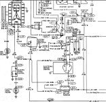
I assume you mean at the ballast feed, and the answer: No-whar. But hey, you wouldn't be the first to do it. Chrysler used that circuit like a two-bit hooker. That's where the voltage regulator's blue wire and the factory idle-stop solenoid take their 12V+ feeds. On the later electrically-assisted chokes, the choke timer also ran off the same circuit as the high side of the ballast resistor. Of course, not all those wires are at the ballast. They're connected by a welded splice buried in the harness. Not coincidentally, all of those wires are blue, except it turns light blue at the VR:

12V+.jpg

The welded splice is shown to the right of CE37.
 
Removing the ballast resistor won't gain you any voltage in start, because in that position the ballast is completely bypassed anyhow. At least it should be. 2- or 4-pin ballast? 4- or 5-pin ECU?
Right but it will boost the run voltage. It's a 2 pin ballast and a 4 pin ECU.

Since your ignition does not fall into the category of "late model" the bold statement does not apply. You'll fry that coil without a ballast resistor. Voice of experience: I had the same coil--8203--in my '81 Imperial 30+ years ago and it lasted less than 15 minutes.
I have definitely run it without a ballast resistor for over 15 minutes. I dunno. Just trying to boost the spark without tearing into the harness and bulkhead just to find nothing that fixes the voltage drop - again. Yeah I chased that one back when I had a different no-start condition on the 400. I cleaned it all up - no help.

7-8V is in the recommended range with the key in the "run" position. In "start" it should be very close to battery voltage, within a volt.
Yes, and it is far below spec now and has been as long as I've had it. Doesn't make it right, but it is what it is for now anyway.

I assume you mean at the ballast feed, and the answer: No-whar. But hey, you wouldn't be the first to do it. Chrysler used that circuit like a two-bit hooker.
I had it connected directly to 12v at the coil before. Trying to avoid that to help with the voltage drop at the coil. No matter where I put it at the ballast or at the coil it's going to make the drop worse. For now I can just open it by hand after the motor fires or just set it so the choke is open all the time.
 
I just checked v at the ballast, nearly 11 in run, 12 in start. Checking at the coil, it's high 4s in run, 7s in start.

The ballast resistor settled down to 0.7 Ohms.

Seems to me that indicates the v drop is between the the ballast and the coil?

There are two wires plugged into each side of the resistor.
 

SiteLock

SiteLock
Back
Top