My 71 Duster work in progress

That might have something to do with why you were able to use the stock z-bar

I bought a new standard one from Brewer's because a) I know TTIs need it and b) TTIs and Doug's aren't even the same design, so c) Doug's don't need it. I'm keeping it clean and won't scratch it up in hope that if it turns out to not fit I can get something back out of it from Wayne toward the TTI modified part.
The only difference in the W2 headers is up at the flange, and the larger primary tubes. I don't know how different the Doug's can be in the area of the countershaft, since there's a limited amount of room and everyone's got to put the collector in the same place. Regardless, I don't think you'll need it, because TTi insisted I did and they were clearly wrong.

B-bodies are the same, at least for 66-up.
Through 1970, yes. Except no. Color me the ignoramus here, but apparently there is a different crossmember for 4-speed only (3-speed uses the automatic crossmember) from 1966-69: 2530668. This changed in 1970, but the '70 B-body is a tough call because the catalog has a gibberish part number (too many digits) that's hard to decipher as any other part in any catalog I have. Either way, it's a biscuit mount and curiously, 1970 uses the same 'member for all transmissions. Of course, the Hemi mount is different. Why? Because it was peened right out of the box for additional strength. The Hemi part number currently supersedes to the standard non-peened aftermarket biscuit number. Either way, this leads me to believe the '66-'69 4-speed crossmember has some difference to it, but either 'member will work since the rear (transmission) mount didn't change type or location.
1971-up B-bodies used the E-body crossmember, which was spool from the get-go (1970). The aftermarket parts applications threw me for a loop because they show a biscuit for '71 B-body, but it's wrong. There was a crossmember revision in June of 1971, but it's spool in either case. Both numbers (before/after the revision) are the same between auto and manual.

The peening is on the crossmember, right? If so, I didn't bend it to get the old mount out, I clamped that bastard in the vise and pried it out with the biggest screwdriver I've got, and did basically the same going back in. So the crossmember is holding the mount like it should unless there's something else to it.
The peening is on the mount itself, hence the different Hemi mount for the same transmissions. About 1,000 year ago, E-Booger printed a factory diagram of the process in Mopar Action, but I can't find it for the life of me (and I'm ill-disposed to digging through 20+ years of magazines at the moment). Anyhoo, it appears to be a worthless discussion since none of the currently-available mounts show the suggested peening as even possible.

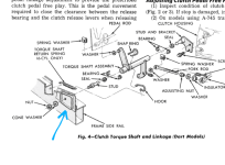
In the diagram below, the red arrow points at an edge on the metal side plate that protruded above the rubber on factory-issue mounts. That edge existed on the non-visible side as well, where the "REAR MOUNT" arrow is pointing. The Hemi mounts had those protruding edges factory-peened over toward (into) the rubber, to discourage the rubber from tearing away from the side plates, i.e. ripping out of the bracket itself. Eyeballing what's available now, those edges and indeed the rubber on one side appears to have been thrifted out of the manufacturing process to save on material costs. In other words, there's nothing to peen anymore. All is not lost, though, because hey--torque specs!
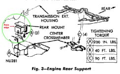
Peen.jpg
 
I've been looking (body and chassis books) for the torque spec on the K-frame bolts, but haven't fond anything. Any help out there?

ETA found this

View attachment 27544
I didn't find that in my 71 books.
K-member bolt torque is 150lb/ft, as shown in the chart found by Estimated Time of Arrival. Why that particular spec doesn't appear in later manuals, I'm not sure, but it's there in the earlier ones. Nothing changed in the A-body front subframe from 1967-'76, so there's no reason to believe the torque changed. As an aside, the 150 number is the "across-the-board" figure for all solidly-mounted K-members.
 
I have this from the FSM
1713018263037.png

I'll keep it in mind to look at the next time I take it out, but I definitely did not peen the mount, nor did I bend the tab in any way.

the chart found by Estimated Time of Arrival

I expand acronyms for a living, cut me a break in the off hours, OK? :coffee:
 
Don't know what it is but I'm making thousands of typos lately, I do either catch most or the computer tells me, but some how still miss some?
 
I've developed a bad habit of having my fingers on the wrong keys recently. As a touch typist I do a lot of backing up and starting over.

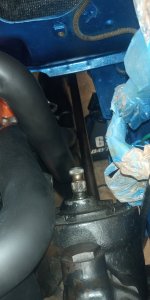
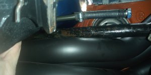
Speaking of which - one tube on the DS header is smack up against the torsion bar, but the bar fits past it and in the socket. On the PS the bar wont line up with the LCA socket because there's a pipe just barely in the way. So it looks like at least the PS header has to come off for a dent.

While I'm accustomed to disappointment I'm going to try to put the clutch linkage in next,

BTW, plumber called today off.
 
While I'm accustomed to disappointment I'm going to try to put the clutch linkage in next,

Mowed the grass instead. Then tried adding 1/4" shim under the passenger side, but that put the passenger side tube directly in the way of the torsion bar so no help there.

Then I took all the shims out of both sides, and now I can get both side torsion bars in, but they're right against the header, but they start in the socket so they will do torsiony things.
20240413_163758.jpg
20240413_163711.jpg
Also the driver's side header is against the steering box again.

That I could live with at least for a while if not forever because I think it would just make some noise, but this I have no idea what's wrong.
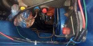
20240413_171131.jpg

Note the pivot balls don't align. If I flip the bracket on the bellhousing over, it's too far back. It looks like the pivot on the bellhousing should just go in that top bracket bolt hole.

I know I've got a photo here somewhere* that shows the casting number on that bellhousing is 3515734, which is a direct fit for 72-up but per Brewer's will work on a 71-back if you use a BSB734 ball stud bracket. This car is a 71, and that bracket you see in the photo is a BSB734.

Now to go try to thread a ball stud into that bellhousing bolt hole.

*I sure can't find it if I do, but I have the convo where I bought it and the subject is "
bellhousing cast # 3515734 works for 67-74 A body and E body with correct fork"

I don't understand how this 71 car is going to line up with that 72 bellhousing that isn't supposed to work.
.
 
Last edited:
BTW, no a ball stud will not screw into the bellhousing bolt holes.

With all the trouble I'm having with a stock rebuild I could never attempt what you guys do, I feel for ya Mann!
Yeah it can be frustrating but that's what hot rodding is I guess.

I told Gina earlier that no way are these things worth the effort. I should've bailed out of this hobby and bought a new Mustang a long time ago.
 
The solution to the headers on the torsion bars may be ratchet straps to pull the headers together.

Back to the pivot balls, while the fenderwell side mount seems untouched from the factory.
20231112_182914.jpg
20231112_183054.jpg
This car has a D31 904 transmission code on the tag. Were those fenderwell brackets welded in on A/T cars?

Since the car came with some big block bellhousings I guess it is possible that the mount was added in the wrong place to accommodate a big block at some point in time. (?)
 
I found out that's not really close to the right place for that to live.
1713118956182.png
So, it was moved to work with a big block at one time or another.
 
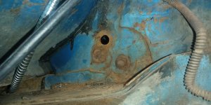
Got lucky - all that was holding the bracket in place was a bolt. They had tried to weld it in a couple of other place but got no penetration into the inner fender well so it fell right off once I took the bolt out.

I'm not a better welder but I do try to dig a little so it would have some penetration. I've got to bang it flatter yet, then weld that booger on. It's in place right now with the stud holding it, and it's where it should be. I guess that other location worked for a big block. Other than that I dunno why it would've been put in the wrong place.

I also managed to get the front end put together and the brakes back on it. to the pedal. I've got a ratchet strap on the headers - the driver's side pulled right over away from the torsion bar and stayed, the other side moved away, but went right back when I took the strap off. I tried it with the ratchet toward both sides, same results either way. I just left the strap on it for the time being.
 
I don't understand how this 71 car is going to line up with that 72 bellhousing that isn't supposed to work.
It is supposed to work. The bracket on the inner fender never changed or moved, nor did the ball stud that it supports. A-body's A-body, as far as '67-up goes. Hell, the countershaft never changed. The only difference is having the correct ball stud for the bellhousing as opposed to year/model.

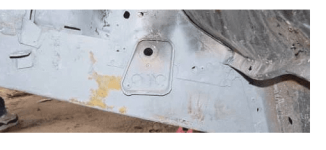
On my car, the inner fender made it blatantly obvious where the bracket was supposed to be located. Remember, they had to make it easy for the drunken UAW guys to get it right. It's not rocket surgery. In fact, I'm sure I have a picture of it somewhere, but I don't believe I posted it in the build thread for that car. As I recall, there's either a dimple or a cutout in overlapping metal that indicates where the ball stud hole needs to be. If nothing else, put the countershaft onto the bellhousing-side ball stud and it should pretty-well point the way to where you need to be. Mark it and look closely. There's something there, albeit on the outside of the inner fender, that told Saucy the Clown how to do it at the factory.

As far as the B/RB stuff goes, unless you're willing to drop a ton on a specific bellhousing, ball stud, spacer and other bits, there's sure to be butchery. My guess is that whomever tried putting a big block/4-speed combination in the car probably tried to align the bracket with the ball stud thread in whatever bellhousing they were using. Then they went back to the automatic because they were in way over their head.
 
As far as the B/RB stuff goes, unless you're willing to drop a ton on a specific bellhousing, ball stud, spacer and other bits, there's sure to be butchery. My guess is that whomever tried putting a big block/4-speed combination in the car probably tried to align the bracket with the ball stud thread in whatever bellhousing they were using. Then they went back to the automatic because they were in way over their head.
I wouldn't be surprised if that's not some secret squirrel way of mounting it for it to work with a B/RB bellhousing (I think it was a 513 from 63) because they had moved it to bolt in through that hole. Nobody would do that on their own just to see what happened and then leave it. Anyway it's all over but the welding now ...

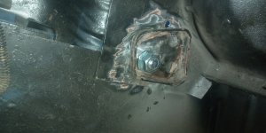
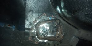
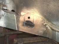
20240414_145232.jpg20240415_104035.jpg20240415_104216.jpg

I've been thinking about it more and might plate the backside of the inner fender. It's down low and won't be seen and would add a lot of strength in place of the three extra holes that is drilled in it. I can even use those holes to weld through (do not weld up the wrong hole Bob).

It also increases my chances of not blowing holes through my inner fender well. The brace is thick so it could be tricky going thick to thin. I can't get to the backside to weld in that direction, thin to thick.

It would've been a lot easier when the engine bay was empty. I never once thought the stupid thing would be in the wrong place, but never really thought about it being an original A/T car until yesterday either.

I put a light behind it in the 3rd photo and you can see the top hole overlaps one of the drilled holes. So something will have to be done or I'll just burn that out.

Note I turned it to match an FSM illustration, not that photo on the car I posted above. Lapping from the fender well down to the frame well like that car is done leaves a gap under the reinforcement the thickness of the inner fender. It also better fits the contour stamped into it.

1713195475440.png
 
Last edited:
I wouldn't be surprised if that's not some secret squirrel way of mounting it for it to work with a B/RB bellhousing (I think it was a 513 from 63) because they had moved it to bolt in through that hole. Nobody would do that on their own just to see what happened and then leave it.
I'm not sure what you mean by "513 from 63" but if you mean a '63 bellhousing, well, an A833 won't bolt to it. The only 4-speed available in '63 was the Borg-Warner T-10, and it only behind 383s in the big-block world. That's why '62-'63 Max Wedge cars were almost all automatics. The only manual was the Borg-Warner T-85, which was a 3-speed and about as easy to powershift as an SM465 in a 1-ton Chevy 4x.

I've been thinking about it more and might plate the backside of the inner fender. It's down low and won't be seen and would add a lot of strength in place of the three extra holes that is drilled in it. I can even use those holes to weld through (do not weld up the wrong hole Bob).

It also increases my chances of not blowing holes through my inner fender well. The brace is thick so it could be tricky going thick to thin. I can't get to the backside to weld in that direction, thin to thick.
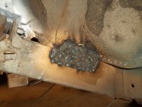
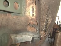
I plated mine, which is to say I doubled the thickness of the sheetmetal in that area. I made a patch out of my old Challenger roof (damn that thing's handy) and put about a zillion holes in it so I could plug weld it as much as possible:

100_1539.JPG

100_1547.JPG


I also put a strip of sheetmetal behind that, similarly drilled and plug-welded, plus adding a bit more metal below/on the flange of that brace to make enough flat space to weld in the bracket (no gap at the welds, but there's a small one at the lower-left corner). That way, the ball-stud reinforcement is welded to the frame. Everything's level. The frame is heavier material than the inner fender, plus it's now more than triple the thickness of even the shored inner fender. I wasn't much concerned about the factory arrangement or looks; my main concern was a stout mounting since at that time I was shopping 3,800lb pressure plates.

Ugly? Absolutely, but it's extraordinarily effective. That's all that matters with a $600 rustbucket '69 Valiant.

100_2839.JPG


As far as blowing holes, unless you've got your welder set on "EVAPORATE" you shouldn't have an issue. I'm not much of a welder myself, but if you favor your arc toward the thicker metal, just nudging a little to the sheetmetal as you go, you won't blow through. It's really very easy--it's not some trick you need to learn--and the filler will flow where you need it. We welded a lot of heavier metal to the factory sheetmetal of that Valiant and the only blow-through we had was when we hit a rusty spot we hadn't seen.

It would've been a lot easier when the engine bay was empty. I never once thought the stupid thing would be in the wrong place, but never really thought about it being an original A/T car until yesterday either.

I put a light behind it in the 3rd photo and you can see the top hole overlaps one of the drilled holes. So something will have to be done or I'll just burn that out.
I'm not sure what kind of welder you have, but everything was done on my car with a 110V welder, be it Stretch's Hobart or my Lincoln, both using CO2 as a shielding gas. Both welders have four heat settings, with "D" being the kill shot. We never used "D", instead using lower settings and adjusting the wire speed a bit to allow more dwell time on the weld without blowing through or enlarging holes when plug-welding thin to thick (between the two of us, we've done approximately 6.4 million plug welds).

This was the penetration I got welding 1/8" plate steel (part of the USCarTool inner-fender brace kit) to sheetmetal with the 110V Hobart MIG, by just favoring the thicker steel while running the weld beads. There are no blow-throughs, only some places where the paint completely ceased to be. Somewhere I have an engine-bay photo taken after I had the full kit installed. There are enough of those black lines to mistake for a road map. Even near the rust, we never once burned through.

100_2770.JPG


In fact, here's a photo in which, despite being a rank amateur welder, I disprove the old adage that you can't weld to rust. You can see how rotten that apron is along its edge, and it had completely let go of the firewall. You can also see the fresh welds. It's still holding five years later! 😄

100_2841.JPG
 
I'm not sure what you mean by "513 from 63" but if you mean a '63 bellhousing, well, an A833 won't bolt to it. The only 4-speed available in '63 was the Borg-Warner T-10, and it only behind 383s in the big-block world.
This is the same thing, it's 1964. Brewer's Performance - Mopar A833 4-Speed Transmission and Component Specialists

The way you reinforced yours is the way I had planned to do it, but with the plate on the inside welded from the outside. My thoughts were to avoid adding metal to the outside because there's already that difference where the inner fender laps over the frame rail.

My welder is a Lincoln 140 with gas.

I have two problems. One, I haven't found a way to clamp anything where I need it. Again I wish I had realized this while the bay was empty. Two, I can't see for crap. I have early stage cataracts, so everything is darker than it should be and it really goes to heck when I strike the arc. I'm basically night blind and shouldn't drive after dark. I can't do anything about that but work with what I've got or pony up the money to have it fixed. This is a source of a lot of my blow-through concern - I don't really see the bead.

For the first problem I would need to run drill screws to hold the two thin pieces together. But with no way to hold that inside piece in place, that ain't likely to work so well. Rare earth magnets might work, then again they might not.

I don't know what I will do on the reinforcement, best I can think of right now is to try to shove it over into place, then zap those two extra big holes to the inner fender to hold it, then finish those holes as good as I can and then weld all around the edge of the reinforcement the best I can. I might be able to run a drill screw through a tiny hole present in the reinforcement, but that's only in one place. Looking at it last night it "looks" like the ball stud bolted in place pulls it back almost far enough but I've got some more flattening to do on the inner fender before I'm happy. And like the clamp, there's no way to swing a hammer on the engine bay side of things.

I've been through plenty of these nobody will ever see it so just weld the crap out of it and get on with it situations. There are at least two places on this car that I intentionally didn't take any photos of. So once I settle on the best I can figure out to do, I'll just do it and it'll be done.

FWIW the reinforcement has some leftover weld on the bottom edge that looks like it was stick welded there from the factory. It almost looks like I can just weld between that edge and the body, so I will definitely give that a shot where I can.

I have a McLeod Super Street Pro clutch/PP in it. I didn't find any specs on the PP. I don't think it's really a super high clamp force part though.

Also, I got the shifter installed and adjusted, and the way too long speedo cable wrapped around, tied back, and installed.
 
I had a problem when gluing my long top of quarter panel in, just wouldn't stay flat & tight, I ended up using self taping zip (drill) screws about every 6 inches, after all was set I removed screws & welded the holes, I know they said not to weld, but I had no choice.
can you get a drill in there?
 
I can only get to the outside, not the inside, and a plate on the outside moves the whole thing further away from the frame rail so I'm trying to avoid that.

The ball stud holds the reinforcement in place pretty good, that might be good enough to get er done.

Before this weekend I will have it welded in one way or another.
 

SiteLock

SiteLock
Back
Top